Deixe a Istar ajudá-lo a iniciar o seu projeto com a nossa experiência e know-how!
Carregue os seus ficheiros de desenho e requisitos de produção e entraremos em contacto consigo no prazo de 30 minutos!

I’ve seen brilliant designs fail for the simplest reasons. One of the most common reasons is when two parts that are supposed to fit together, don’t. This article is about making sure that doesn’t happen to you. We are going to talk about slip fits. This is when you want a pin to slide smoothly into a hole. We will cover the details of slip fit tolerances and geometry. You will learn how to design parts that assemble easily and work perfectly every time. This guide will save you time, money, and a lot of headaches.
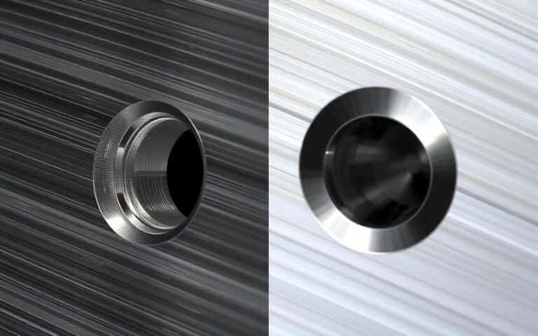
Let’s start with the basics. What are slip fits? Imagine a key sliding into a lock. It goes in smoothly without being too loose or too tight. That’s a slip fit. In engineering, it’s a type of clearance fit. This means there is always a small gap between the two parts, like a pin and a hole. This gap is what allows the parts to slide together without force. The goal is to achieve the right fit and function for your assembly.
Good slip fits are essential for parts that need perfect alignment. Think about a component that needs to be located precisely before being bolted down. A dowel pin with a slip fit can do this perfectly. It makes assembly much faster and more accurate. When you are aligning tight geometry, you need a reliable method. Using slip fits is one of the best. The importance of these basics will illustrate their necessity as we go deeper.
So, how do we create these perfect slip fits? The secret is in the tolerance. A tolerance is the acceptable amount of error in a dimension. No part can be made to an exact size. A tolerance tells the machinist how much bigger or smaller a feature can be and still be good. A slip fit tolerance is the specific range of sizes for a pin and a hole that creates the desired sliding fit.
Let’s say you have a 0.5-inch pin. For a slip fit, you might design the hole to be 0.501 to 0.502 inches. This small gap ensures the pin can always slide in. At its smallest, the hole is still 0.001 inches larger than the pin. At its largest, the gap is 0.002 inches. This range is the tolerance. At this level, tolerancing is simple. You just mark a dimension on your drawing with its allowed variation. This is the foundation of good fit design.
Early in my career, I learned a tough lesson about tolerancing. We were making a large fixture. I was proud of the design. But I specified excessively tight fits for some alignment pins. I thought tighter was better. I was wrong. When the parts came back from the machine shop, nothing fit. We had to spend hours carefully sanding and reaming holes on the assembly floor. It was a mess.
That day, I learned linear tolerances are a balancing act. You must avoid tight tolerances unless they are absolutely necessary. But you also can’t have the loose tolerances which would make the assembly sloppy. The goal is to find the right tolerance for the job. This experience taught me to think about the entire assembly process, not just the design on my screen. It’s a key part of the whole design process. In my career, I have also explored interference fits, where the pin is larger than the hole. But for parts that need to come apart, slip fits are the way to go.
Size tolerance is only half the story. The other half is geometry. This is where we talk about things like straightness, flatness, and position. This is often called GD&T, or Geometric Dimensioning and Tolerancing. It’s a system that controls the shape and location of features. For slip fits, one of the most important geometric controls is perpendicularity.
Imagine a hole with a perfect slip fit tolerance. The hole diameter is exactly right. But what if the hole is drilled at an angle? The pin won’t go in. It will bind up. The hole must be perpendicular to the surface it goes into. We need to specify how perpendicular it must be. The same is true if the hole is off-center. Even with the right size, a misplaced hole will ruin your alignment.
The drawing looks at the geometry of the part. The geometry and describes the ideal location and orientation of features. But we know the part will never be ideal. So, we add a tolerance to the geometry, too. This tells the machinist how much the hole’s angle or position can vary. This control is critical for making good slip fits.

Dowel pins are the heroes of precision alignment. When you are using dowel pins, you want them to work perfectly. A true slip fit is what you need. This means the pin slides into the hole with just a little push from your hand. It should feel smooth, with no wobble and no binding. This is how you give you a self-locating assembly.
The big question of how tight to make the fit comes up often. My rule is this: if you need a hammer, it’s too tight. Tight is too tight when it deforms the parts or makes disassembly impossible. A good slip-fit has just enough clearance for the parts to slide together easily. For a standard dowel pin, a total clearance of 0.0005 to 0.0015 inches is a good starting point.
Dowel pins are perfect for creating a repeatable alignment. When you design a part that uses them, you are creating a system that can be taken apart and put back together in the exact same position. This is why getting the slip fits right for these pins is so important. It makes the final product more robust and easier to service.
Let’s discuss the original topic in more detail. The term slip fit tolerances and geometry describes the complete picture. You cannot think about one without the other. A perfect slip fit tolerance is useless if the geometry is wrong. And perfect geometry is useless if the size tolerance is wrong. They are a team. You need to translate these design considerations onto your engineering drawings so the machinist knows exactly what you need.
Think about a cylinder head bolting onto an engine block. The bolting onto an engine block needs perfect alignment to seal correctly and prevent leaks. Often, slip-fit dowels may be used to locate the head before the bolts are tightened. The block needs to be exactly in the right spot. The slip fits for these dowels must be precise. The holes must be in the right place and perfectly straight.
This is a high-stakes example of where slip fits are critical. The tolerance on the hole size might be just a few ten-thousandths of an inch. The positional tolerance for the holes might be just a few thousandths. We get into the question of how much variation is acceptable. We must look at how much variation we can tolerate for the assembly to work. This is the core of designing with slip fits.
When we talk about the location of a hole, we often use a tolerance called true position. In the old days, we would put a tolerance on the X and Y dimensions from an edge. This created a square tolerancing area. But a drill bit is round. It’s more likely to wander in any direction, creating a circular pattern of variation.
True position is a modern way to define location tolerance. It defines a round zone around a perfect, “true” position. The center of the hole must lie inside this circle. This is a more realistic way to control hole location variation. A key benefit is that it actually gives the machinist more tolerance. A circle with a certain diameter has more area than a square that fits inside it. For example, a circular tolerance zone of 0.020 inches gives 57% more tolerance area than a +/- 0.007 square zone. This means the pin is centered in its ideal spot, and the true position tolerance defines how far it can drift.
This helps the manufacturing team has as much room as possible to make a good part. It makes it easier for them to hit the tolerance, which lowers costs and improves quality. It’s a smarter way to handle the location of critical features for slip fits.
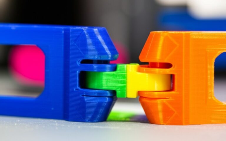
Using one dowel pin is simple. But when you use two dowel pins, things get more complex. Now, not only do the holes need the right slip fit tolerance, but the distance between them must also be very accurate. This is a common challenge in precision alignment. The first hole slipping in is easy, but the second one often binds if the spacing is off.
This is where we must use a datum system. A datum is a reference point, line, or plane from which we make our measurements. On a block, we might mark the bottom surface as datum A. Then we can use the front and side surfaces as datums B and C. All the critical features of the block are then measured from these datums. This ensures that the location of the two holes is controlled relative to each other, not just from the edges of the part.
When you use a datum reference frame, you ensure that the variation compared to the ideal location is tightly controlled. You might have one hole as a tight slip-fit to fix the location, and the second hole with a slightly looser tolerance to allow for small variations in the distance between the pins. This is a common strategy for aligning tight geometry with two pins. We need to make sure the possible for the geometry to work even with manufacturing variations.

Yes, there are some great tricks. Let’s talk about blind holes. These are holes that do not go all the way through a part. If you press a pin with a tight slip fit into a blind hole, you trap the air inside. The air compresses and pushes back, preventing the pin from seating all the way. I’ve seen people struggle with this, thinking the fit was too tight.
The solution is simple: you have to allow room for the air to escape. There are two common ways to do this. You can add a small vent hole that connects to the bottom of the blind hole. Or, you can grind a small flat on the side of the pin. This is often called an air release flat-ground. This tiny channel lets the air to escape as the pin goes in.
This is a small detail, but it makes a huge difference. The assembly will be easier and more reliable. It’s a perfect example of thinking through the entire assembly process, not just the numbers on the drawing. It’s much easier when you allow room for real-world physics to do its thing.
My final piece of advice is this: be kind to your machinist. Your job as a designer is to create a part that works. Their job is to physically make it. You can make their job easier and get better parts by being smart about tolerancing. The most important rule is to give them as much tolerance as possible. Don’t specify a tolerance that is much tighter than what you actually need.
Tighter tolerances cost more money. They require more setup time, slower Maquinação CNC speeds, and more inspection. This all adds up. Before you call out a very tight tolerance, ask yourself if it’s truly necessary for the fit design. Often, a slightly looser slip fit will work just as well and be much cheaper to produce.
When you create your drawings, be clear. Use standard methods for tolerancing. The goal is to make sure the manufacturing team has as much information as they need, and as much flexibility as the design allows. When you translate these design considerations clearly, you reduce errors and build a better relationship with the people who make your ideas a reality.