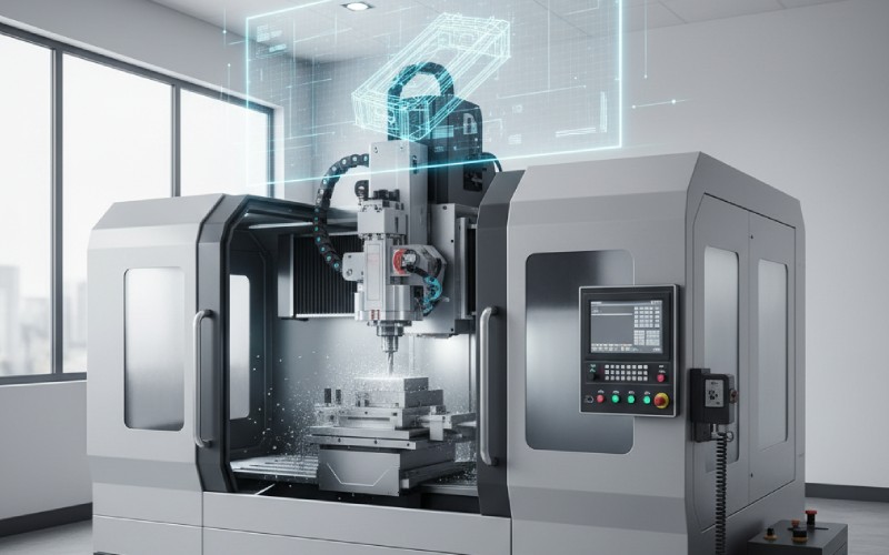
Tecrübemiz ve bilgi birikimimizle Istar'ın projenize başlamanıza yardımcı olmasına izin verin!
Tasarım dosyalarınızı ve üretim gereksinimlerinizi yükleyin ve 30 dakika içinde size geri dönelim!
For a long time, I have worked on many projects. A mistake I see a lot is when parts twist and bend more than they should when a force is put on them. This happens when designers and engineers do not pay enough attention to a key feature: torsional rigidity. This article is for you if you want to make your designs stronger. We will look at easy ways to increase the torsional rigidity of any part. You will learn how to pick the right material and the best shape. This will help you make better things and solve common structural problems. This is a simple guide to help you improve your design skills.
From what I’ve seen, it’s best to start with an easy explanation. Torsional rigidity is a measure of how well an object can stop itself from being twisted. Think about twisting a wet towel to get the water out. The work it takes to twist the towel is like its torsional rigidity. It would be much harder to twist a steel bar. The steel bar has a much higher torsional rigidity. This resistance to twisting is a very important feature in many mechanical designs. When you apply a twisting force, which we call a torque or a torsional load, the object will twist a certain amount. This amount is an angle. Torsional rigidity tells you how much torque is needed to make a certain amount of twist.
Why should you care about this for your design? If a part in your design has low torsional rigidity, it can lead to serious issues. It might bend or twist too much when a normal load is on it. This can cause bad performance or even make the part break. For instance, a car frame with low torsional rigidity will flex and twist on rough roads. This makes the car hard to control. In a machine, a shaft with low torsional rigidity can cause vibration and damage. Knowing about and controlling torsional rigidity is very important for making a safe and strong structural design. Every engineer should know this. This article will help you learn this key subject.
A good design always thinks about the forces that will act on it. A torsional load is a very common kind of load. The torsional rigidity of a part decides how it reacts to this load. The main goal is to control the amount of twist. By focusing on torsional rigidity in design, you can make parts that are stiff and strong. This can also help you optimize your design by using less material, which saves weight and money. The idea of torsional rigidity is a great tool for any engineer.
You do not have to be great at math to learn the basics of torsional rigidity. We can calculate it using a simple formula. I have used this easy equation many times to get a good idea of a part’s stiffness. The torsional rigidity is often shown by the letter ‘K’ or sometimes as ‘GJ’. The main idea is that you multiply two important things: how stiff the material is and how stiff the shape is.
The main formula you will see is:
Torsional Rigidity (K) = G * J
Let’s look at what this means. ‘G’ is the Shear Modulus of the material. The shear modulus is a value. It tells us how well a material can fight against shear stress, which is a sliding or twisting type of stress. A bigger shear modulus means the material is stiffer against torsion. ‘J’ is the area moment of inertia. This value tells us about the shape of the part’s cross-section. It shows how the shape helps it to stop a torsional load. A larger ‘J’ value means the shape is better at fighting a twist.
So, if you want to increase the torsional rigidity of your design, you have two main things you can change. You can pick a material with a higher shear modulus (G). Or, you can change the design of the part’s cross-section to get a larger area moment of inertia (J). We will look at both of these choices in this article. This simple equation is the starting point for a lot of great structural design work. It helps us check problems and find ways to solve them. You can calculate how much an object will twist with a certain torque over a certain length using the following formula: Twist Angle = (Torque Length) / (G J).
Picking the right material is a very important choice you make at the start of any design process. If you want to improve torsional rigidity, you should find a material that has a high shear modulus (G). The shear modulus, which is also called the modulus of rigidity, directly changes the torsional rigidity. A higher modulus means a stiffer material when a torsional load is on it.
Let’s look at some common materials. Metals like steel have a very high shear modulus. This is why steel is used a lot for shafts, frames, and other parts that get a heavy torsion load. Aluminum is another good material. The shear modulus for aluminum is about one-third of steel’s. But aluminum also weighs a lot less. So, for the same weight, an aluminum tube can often be designed to have a higher torsional rigidity than a solid steel rod. It is all about how you use the material properties in your design.
Plastics and special materials have many different shear modulus values. Some new materials can have a very high modulus. This makes them great for things that need to be light but also have high performance. The important thing is to look at the information sheets for the material properties. Do not just guess. As an engineer, you need to compare the shear modulus of every material you are thinking about using. Your choice will make a big difference in how well your part works in the end. A simple table can help you compare materials.
| Malzeme | Shear Modulus (G) in GPa | Notlar |
|---|---|---|
| Çelik | 77 – 80 | Very stiff, but heavy. Good for a high load. |
| Alüminyum | 26 – 27 | Good stiffness for its weight. |
| Titanyum | 41 – 45 | Strong and light, but costs more. |
| Plastic (ABS) | ~1 | Not very stiff, but very light. Good for parts with a low load. |
Yes! I believe that changing the shape is often the best way to improve torsional rigidity. This is where a smart design can really make a difference. As we saw in the formula, the torsional rigidity is based on ‘J’, the area moment of inertia. This value is all about the shape of the cross-section. A small change in the shape can cause a very large increase in torsional stiffness.
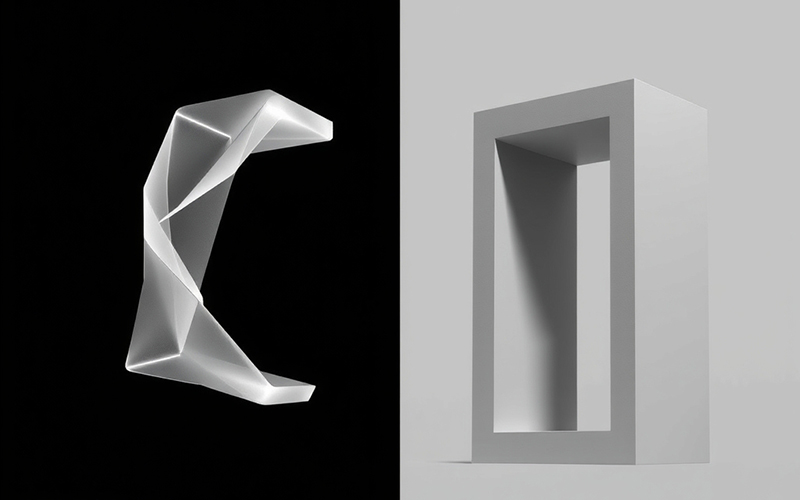
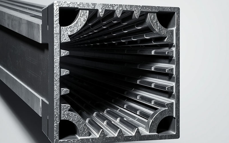
Think about a flat ruler. It is easy to twist. Now, think about a round pipe or a square tube. They are much harder to twist, even if they are made from the same amount of material. This is because their geometry is better for fighting torsion. The material is spread farther away from the center axis of the twist. This makes the ‘J’ value go up by a lot. The best shapes to get a high torsional rigidity are closed shapes, like a tube or a box beam. An open shape, like an I-beam, is good for a bending load. But it is not very strong when you apply a twisting force on it.
When you are designing for torsional loads, you should always try using closed sections. A round tube is the best shape for just torsion. It stops twisting the same from all sides. A square or rectangular tube is also very good. The difference between an open shape and a closed shape can be 100 times or more in torsional rigidity. This is a simple but very important idea. By making the geometry of your part better, you can get a much higher torsional rigidity. You can do this without adding weight or using a more expensive material. This is a good way to optimize your design.
The thickness of a part’s walls has a very big effect on torsional rigidity. This is especially true for a tube or hollow shape. I have seen many new engineers make a part’s wall a little thicker to make it stronger. They do not always know just how much it helps with torsional resistance. The ‘J’ value we talked about changes a lot with the outside size and the wall thickness of a hollow part.
For a hollow round tube, the ‘J’ value is calculated using the outer size and the inner size. Because of the way the math works, a small increase in the size or thickness of the tube gives a very large increase in torsional rigidity. If you double the diameter of a solid shaft, its torsional rigidity becomes 16 times bigger! This shows how powerful changing the size can be.
This is a key technique when you need to optimize a design. If your part is twisting too much, check if you can make its diameter bigger. This is often a better and cheaper way to solve the problem than just using a stronger material. A larger, thinner tube will nearly always have a higher torsional rigidity than a smaller, solid rod that weighs the same. This easy rule is used in the design of many things, from bike frames to airplane wings. Your job is to control the stress and deformation under a load. Using thickness in a smart way is a great way to do that.
The best method I know to use these ideas is to think about torsional rigidity right from the start of the design process. Do not wait until you find a problem with a part that twists too much. Thinking ahead saves you a lot of time and money. Start by asking yourself, “Will this part have a torsional load on it?” If the answer is yes, you need to make a plan.
Here is a simple list of steps you can apply:
By following these steps, you make torsional rigidity a main part of how you think about design. This helps you stop problems from happening later. It is a planned way to improve the structural strength and the general performance of your work.
After you have a basic design, you need to analyze it to see if it will work as you want. Then, you can make it better, or optimize it. A long time ago, this needed a lot of hard math. Today, we have great tools that make this analysis much simpler. The most common tool is called Finite Element Analysis (FEA). FEA is a computer-based technique. It can show how a part will act under different kinds of load, including torsion.
With FEA software, you can make a computer model of your part. You can then apply a pretend torsional load to it. The software will calculate the stress, strain, and deformation all over the part. It can show you exactly how much the part will twist. It also shows you where the areas of high stress are. This is very helpful information. It helps you find the weak places in your design before you make anything real. This kind of analysis is a very important step to optimize a design.
Using the results from your analysis, you can then make the design better. If the part twists too much, you can try different things in the software. You can change the material to one with a higher shear modulus. You can increase the wall thickness. You can add parts like ribs or supports to increase the torsional stiffness. You can quickly test many different ideas to find the best possible design. This lets you analyze and improve torsional performance in a very good way. This is a new way to solve engineering problems.
After you know the basics about shape and material, there are other special, advance ways we can use for hard torsional load problems. One great technique is to use special materials called composites. Composites, like carbon fiber, let you choose the direction of the stiffness. You can place the fibers at a 45-degree angle to the part’s main axis. This setup is perfect for fighting a torsional load. It gives the part a very high torsional rigidity for how much it weighs.
Another advance technique is to look closely at stress concentrations. When a part has sharp corners, holes, or quick changes in shape, the stress from a torsional load can build up in these small spots. These stress concentrations can cause cracks and breaks, even if the total stress in the part is low. To fix this, you should use smooth, rounded corners in your design. This helps the stress spread out. This will make the chance of it breaking much lower.
Last, in a big project with many parts, the way you connect them is very important. A connection that is not strong, like a bad weld or bolts that are not tight, can wreck the torsional rigidity of the whole thing. Make sure your connections are designed to move the torque well from one part to the next. A strong weld or a well-made connector can make a big difference. These advance ideas are what make a good design into a great one. The plan is to make a strong, unbroken path for the torsion to go through.
When I learn something new, I like to look at examples from the real world. Seeing how other people have solved problems is a wonderful way to learn. For torsional rigidity, there are many great case studies right around you. Look at the design of a new car. The frame is a great example of a part designed for very high torsional rigidity. Car companies often tell people their car’s torsional rigidity number. This is because it is directly related to making the car safer and easier to drive.
Another place to find great case studies is in the airplane industry. An airplane wing has to fight against a very large torsional load when it is flying. Engineers use smart designs with supports inside. These all work together to make a wing that is light but also very stiff. You can find many articles online that talk about these designs. They are a great resource for learning how to handle torsion.
For a more official reference, I always suggest a good school book on the mechanics of materials. These books have whole sections just about torsion. They will give you the detailed formulas, lists of material properties, and examples that you need. They are a very helpful resource for any engineer. I suggest you look for a book with many real-world examples. This makes it easier to use the ideas in your own design work. Do not be afraid to study the basics again; a strong base of knowledge is needed for good engineering.
In this article, we have talked about ways to improve torsional rigidity. Let’s put it all together to see how we can solve common problems. The problem I see most often is a part that twists too much when it’s being used. This extra deformation can make a machine not work right or feel weak.
The first step to solve this is to analyze the problem. Is the torsional load bigger than you first thought? Is the material not as stiff as you believed? Or is the geometry of the cross-section just not a good shape for torsion? When you find the real reason for the problem, you can apply a fix. If the shape is the issue (like an open C-shape), the best fix is to change the design to a closed shape, like a tube. This will give you the biggest improvement.
If the design shape is already good, then you can check the material and its size. Can you change to a material with a higher shear modulus, like changing from aluminum to steel? This will give you a direct increase in torsional rigidity. Or, can you increase the part’s diameter or wall thickness? As we talked about, even a small change here can make a very big difference. By using a mix of these ideas, you can almost always find a way to solve problems with low torsional rigidity. This will help you make a design that is strong and that you can count on.
Here are the most important things to remember from this article: