Let Istar help you get started on your project with our experience and know-how!
Upload your design files and production requirements and we will get back to you within 30 minutes!
For years, I’ve used the dependable, common green boards known as rigid printed circuit boards. They have been the foundation of many electronic devices I’ve helped create. But as technology advanced, needing smaller, lighter, and more complex designs, I ran into a problem. The stiffness of the traditional circuit board was becoming a real issue. That’s when I started learning all about flexible PCBs, and it totally changed my view on what you can do in electronics design.
This article is for anyone who wants to go beyond normal electronics, just like I did. We’ll look at the details of the flexible printed circuit board (FPC), a technology that lets circuits bend, twist, and fold. You will learn about the materials that make them special, the different kinds you can use, and the amazing benefits they bring. I’ll share what I’ve learned to show you why knowing about the flex PCB is now essential for anyone serious about modern electronics.
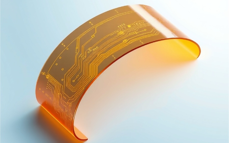
I still remember the first time I saw a flexible printed circuit board. It seemed less like hardware and more like a futuristic ribbon. A flexible PCB is basically a layout of electrical pathways on a thin, bendable base material. Imagine a circuit board that can bend and twist without damaging the connections. Unlike the stiff ones, these circuits are made to fit the shape of the product they are inside. This main feature is what makes the flexible circuit a key part of modern, small electronics.
A flexible printed circuit board does the same job as any PCB: it connects and holds electronic parts. But, the way it’s built on a flexible substrate, usually a polymer film, is what makes it different. This allows a flex circuit to be used where a rigid circuit board can’t, like connecting parts that move or fitting into odd-shaped areas. The technology has been around for a while, but it has grown very quickly because of the need for smaller and more portable electronic devices.
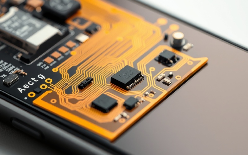
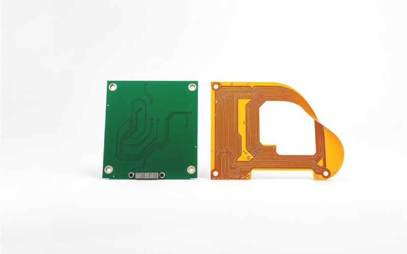
When I began looking into flexible electronics, the clearest difference was, of course, that it could bend. But as I learned more, I saw that the differences are much more than just being bendy. A rigid PCB uses a solid, stiff base, often FR-4, which is a type of fiberglass material. This makes it strong and steady. A flexible PCB, however, uses a bendable base material like polyimide, which lets it bend and flex. This basic difference in materials decides how they are used; rigid PCBs are great for big products like desktop computers, while flexible PCBs are vital for small devices like smartphones and wearables.
The way they are made also has key differences. For example, instead of a solder mask, a flex circuit usually uses a “coverlay,” which is a bendable protective film for the circuitry. Cost is another big factor. At first, a flex circuit often costs more to make than a rigid circuit board. But, because it can make products smaller and get rid of the need for connectors and wires, you can end up saving money on assembly costs and materials. I’ve seen that these “hidden savings” often make the flexible PCB a smarter money choice for complex designs.
What makes a flexible PCB special are the materials used to build it. The materials you choose directly affect the board’s ability to bend, how long it lasts, and how it handles heat. In my experience, it’s very important to understand these materials to design a product that works well and lasts a long time.
Here is a list of the main materials used:
| Material Component | Description | Common Materials |
|---|---|---|
| Substrate (Base Material) | This is the bendable foundation of the circuit board. It keeps things insulated and gives it shape. | Polyimide (PI): The most popular choice because it’s very flexible, handles heat well, and resists chemicals. Polyester (PET): A cheaper choice with average heat resistance, often used in everyday electronics. |
| Conductor | This material creates the electrical pathways, or traces, on the board. | Copper: The most common conductor. It can be Electrodeposited (ED) or Rolled Annealed (RA). RA copper is more bendable and is better for parts that move a lot. |
| Adhesive | This layer glues the copper conductor to the substrate. Some new designs are “adhesiveless” for better performance. | Epoxy & Acrylic: Common choices for gluing layers. Adhesiveless types bond the copper right to the polyimide, making it thinner and more flexible. |
| Coverlay/Covercoat | A protective layer put over the circuitry, similar to the solder mask on a rigid PCB. | Polyimide Film: Often used with a glue to insulate and protect the circuit from the outside world. |
| Stiffener | Some parts of a flexible PCB need extra support for mounting components. A stiffener is added to these spots. | FR-4 or Polyimide: Thicker bits of these materials are added to make certain spots stiff, without losing the overall bendiness. |
The base material I’ve seen most often is polyimide (PI). The fact that it can withstand high temperatures makes it very strong for tough jobs. The conductor is nearly always copper, which is etched to form the circuit patterns. A thin protective coating, like ENIG (Electroless Nickel Immersion Gold), immersion silver, or immersion tin, is then put on to stop rust and help with soldering.
Just like rigid boards, flexible PCBs come in a few different types, and each is good for different things. I’ve learned that picking the right kind of flexible circuit is very important for how well the final product works and how much it costs. They are usually sorted by how many conductor layers they have.
Here are the common types of flexible circuits I use a lot:
There are also special kinds like HDI (High-Density Interconnect) flexible PCBs. These use very thin materials and micro-vias for products that need the best performance and the smallest size.
When I first started using flexible PCBs for some of my projects, the advantages were clear right away. It wasn’t just about being able to bend; it was a basic change in design freedom and how well things worked. The many advantages of a flexible printed circuit board can be a big deal for making new products.
Here are some of the main benefits I’ve seen myself:
The process for making a flexible circuit board is similar in some ways to making a rigid PCB, but with important differences because the materials are bendable. Knowing these basic steps has helped me design flexible circuits that are easier and cheaper to make.
The process usually includes these main steps:
I am often asked about rigid-flex PCBs, and it makes sense. They are a powerful step forward in circuit board technology. A rigid-flex PCB is a hybrid board that has the best features of both rigid and flexible circuits. It is made of rigid circuit board parts that are smoothly joined by built-in flexible circuits. This makes one single PCB that can be bent or folded to fit the shape of the final product.
The biggest benefit of a rigid-flex PCB is that it gets rid of the need for standard connectors, cables, and the solder joints that usually link separate rigid boards. This not only saves a huge amount of space but also makes the system much more reliable by removing spots that could fail. I have found that rigid-flex designs are great for complex, high-stakes products where space is tight and it needs to be very durable.
So, when is it a good idea to choose a rigid-flex design? I suggest them for complex jobs that need to be very reliable, where space is limited and toughness is key. Examples include military equipment, aerospace systems, and advanced medical devices like pacemakers. Even though making them at first is harder and costs more than a standard flex or rigid PCB, the easier assembly, lighter weight, smaller size, and better reliability often make the extra cost worth it.
The use of flexible PCBs has grown very fast in the last ten years. Their special ability to save space, be lighter, and handle shaking has made them essential in almost every part of the electronics industry. I’ve had the chance to see them used in a huge range of products.
Here are some of the most common areas where flexible printed circuits are used:
Making a design for a flexible circuit board is different from making one for a rigid board. I found this out the hard way on one of my first projects. To make sure it’s dependable, especially for parts that bend a lot, there are certain design rules you need to follow. If you ignore these, the electrical paths can crack and fail early.
Here are a few very important rules I always follow when making circuit board designs with bendable parts:
Talking with your manufacturer is also very important. They can give you specific DFM (Design for Manufacturability) rules based on how they make things and the materials they use.
You can’t deny the trend: flexible PCBs are not a special technology anymore; they are a common solution. From where I stand in the electronics industry, the reasons they have become so popular are obvious. It’s a combination of what the market wants and improvements in technology. The constant push for smaller, lighter, and more powerful electronics is the main reason. A normal rigid PCB with its large connectors just can’t fit into the small spaces and meet the weight limits of today’s wearables, new smartphones, and IoT sensors.
Also, the reliability of a flexible circuit board has been proven in the toughest places, from inside a person’s body to outer space. As industries like cars and medical devices use more advanced technology, the need for strong and dependable connections that can handle shaking and constant movement has grown a lot. The ability to create complex, 3D circuit board designs has also started a new wave of new ideas, letting engineers and PCB designers be more creative.
Lastly, even though the materials might cost more, the total cost to own them is often lower. Using fewer parts (like cables and connectors) and making the assembly process easier means lower assembly costs and fewer chances for mistakes. As the ways of making them get better and easier to access, I believe we will see the use of flexible and rigid-flex PCBs grow even more, forming the future of advanced electronic products.