Let Istar help you get started on your project with our experience and know-how!
Upload your design files and production requirements and we will get back to you within 30 minutes!
If the L-shaped brackets are wrong, every clever thing you did above them is just waiting for its moment to fail.
You already know what an L-shaped bracket is, how the catalogs describe them, and you have seen the usual load charts and product photos. You probably skimmed more than one guide on sheet metal brackets, general bracket styles, and “beginner’s” angle bracket content.
This piece is for the time after that. When you are past the definition stage and more interested in why two almost identical brackets behave very differently once you actually bolt them into a project.
The focus here is simple: treat the L-shaped bracket as a short structural member with a messy life, not as a decorative right angle. The moment you do that, selection and design decisions start to change.
Ignore the marketing for a moment. Picture a basic model: one leg fixed, one leg loaded, and a filleted corner between them. Finite element work on standard L-bracket geometries shows what you already suspect: most of the drama lives right around that inside corner and the zone near the first row of fastener holes.
So a “good” L-shaped bracket, in practical terms, tends to do a few quiet things. It keeps the load path short by avoiding needlessly long cantilevered arms. It uses a generous inside bend radius instead of a sharp fold that spikes stress. It leaves enough material between each hole and between holes and edges to avoid tear-out before the steel itself yields. Those patterns hold whether you are talking about a small furniture corner brace or a heavy structural angle holding up a machine shelf.
Once you think of the part this way, you stop asking only “what is the advertised capacity?” and start asking “where, exactly, will this one try to crack first?”
Manufacturers do serious testing. But their numbers live in controlled setups that do not look much like a slightly crooked wall stud or a hollow-core panel. Heavy-duty L-brackets for shelving, for example, may be listed at 1,200 lb per pair when installed to solid blocking with proper anchors and edge distances.
In the field, you get different realities. One leg lands on two screws into a soft stud. The other leg bears on a shelf that is already sagging. The load is not purely vertical; someone climbs on the shelf from the side. The bracket is rarely the only weak point, yet it is often treated as if its test capacity alone defines the system capacity.
A more useful way to read those numbers is as an upper bound in a best-case setup. Then you mentally apply discounts for each thing that is less than ideal: dubious substrate, eccentric loading, casual fastener choice, corrosion, repeated impacts. The exact percentage is up to your risk appetite, but the habit matters more than the math.
If you are specifying brackets for critical shelving, machinery, or racks, try to reference both the bracket’s rating and any relevant standard or test method behind it. That background is often hinted at in better technical sheets, even if the glossy product page hides it.
Standard L-shaped brackets are bent to 90°, but there is nothing magical about that angle. Sheet metal shops routinely form L-style brackets up to around 120° when the material and thickness can tolerate the bend without cracking. Less ductile alloys and thicker gauges resist tight or extreme angles, so trying to force “one angle for everything” is not always wise.
The length of each leg should be thought of not just as “how far do I need to reach” but “how much moment am I creating at the bend and at the fasteners.” A slightly longer vertical leg that picks up more fasteners into solid structure often improves performance more than a longer horizontal leg that only adds leverage.
Hole layout is where many off-the-shelf parts quietly disappoint. Holes clustered close to the bend reduce section modulus exactly where you wanted strength. Holes too near the edge can fail by tear-out at loads well below the material’s nominal strength. Guidance from sheet metal bracket design resources tends to stress planning hole size and spacing in tandem with the intended fastener and substrate, not as an afterthought.
So when you compare two brackets with the same thickness and material, look first at the bend radius and hole pattern, not only at leg length or finish.
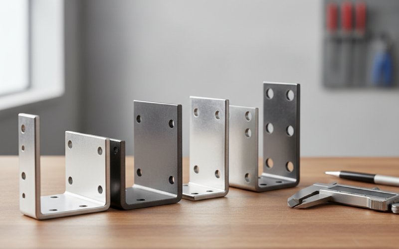
From most sheet metal shops you will see familiar options for L-shaped brackets: mild steel, stainless, aluminum, sometimes brass. Each responds differently once bent and loaded. Steel brackets, especially in structural grades, give you stiffness and strength at modest thickness and cost. Stainless versions trade some cost and bending effort for corrosion resistance and cleaner appearance. Aluminum brackets offer low weight and good corrosion resistance but can require thicker sections or gussets to hit the same stiffness, particularly in long-leg designs.
Surface treatments follow the use case. Indoor light duty brackets may get away with simple powder coating. Outdoor or damp environments lean toward galvanized or stainless designs, especially where roof interfaces, decking, or cladding are involved. Resources aimed at construction brackets and angle connectors routinely emphasize corrosion protection near roofs and exposed joints because moisture and trapped debris quickly erode unprotected steel.
The subtle point here is that finish cannot recover a fundamentally weak geometry. Plating a marginal bracket does not change the stress concentration at its bend or the edge distance at its holes.
Not all L-shaped brackets live the same life. Some are mostly cosmetic alignment aids; others carry long-term, fluctuating loads. Bringing that into one view helps.
| Use case | Typical L-bracket style | Material / finish tendency | Notes on behaviour |
|---|---|---|---|
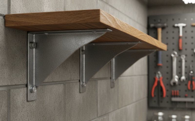
| Heavy wall shelving into studs | Deep L-bracket, sometimes with gusset | Thick steel, powder coated or galvanized | Bending at the inner corner and fastener withdrawal usually govern before pure material yield. |
| Furniture and cabinetry corners | Small angle brace | Thin steel or stainless, often plated | Often governed by screw tear-out in the wood more than by bracket strength. |
| Floor-mounted column or frame | Floor L-bracket with one leg anchored to slab | Structural steel with hot-dip galvanizing in wet areas | The bracket becomes a base plate; anchor sizing and spacing into concrete dominate performance. |
| Electronics enclosure internals | Compact L-bracket or custom angle | Aluminium or thin steel with passivation or paint | Stiffness matters more than ultimate strength; avoiding resonance and vibration issues is the aim. |
| Retail product dividers on shelves | Low-load transparent L-form | Acrylic or clear plastic, no heavy coating | Geometry focuses on guiding products, so abrasion and impact resistance beat pure load capacity. |
This is still the same basic letter “L”, but the design priorities shift completely once you put the part in context.
Quite a few parts are functionally L-shaped brackets wearing different names. Floor brackets, for instance, are essentially L-shaped supports built to sit on the floor and tie vertical members down. They keep the short leg on the floor and the long leg up the column, turning uplift and lateral loads into tension and shear in the anchors.
Adjustable angle brackets and slotted L-brackets show up in builder catalogs too. They start as an L, then add slots or hinge-like features so you can shift the angle or location before locking it in with screws or bolts. This flexibility is useful when the as-built geometry does not quite match the drawing. The structural trade-off is obvious: material removed for slots means more careful attention to net section, especially near the root of the bracket where stress is already high.
Many gusset brackets are really reinforced L-brackets with an extra triangular web between the legs. Sheet metal design articles often present them as “L plus triangle,” with the gusset either welded in or formed as part of a single piece. That extra material reduces deflection at relatively low increase in weight, a pattern that FEA studies on L-brackets confirm when optimizing brackets for shelf support and industrial applications.
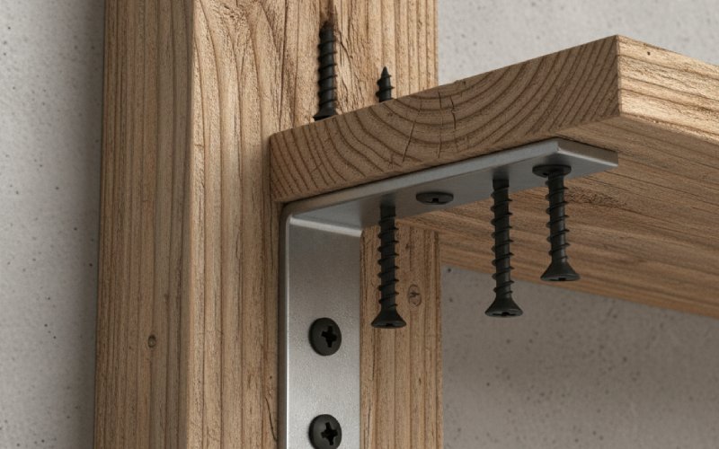
Good L-shaped brackets can still be used badly. Most real failures trace back not to exotic material flaws but to plain issues: poor anchoring, mismatched fasteners, or geometry that clashes with the surrounding structure. Guides for shelving systems, for example, quietly insist on fixing L-brackets into studs rather than just drywall, and on using one bracket per stud along the top shelf to stop the system peeling off the wall.
Fastener diameter relative to hole diameter is another simple point with large consequences. A loose fit means the bracket can move slightly before the screw bears, which amplifies local bending and can lead to elongated holes. Too tight, and installation becomes finicky, leading people to substitute different screws on site.
Edge distances and embedment depths are often dictated by building or product standards, but you still see real installations where the bracket is fine and the fixing pattern into the substrate ignores those rules. Thin masonry, crumbling concrete, or soft timber near the surface change the effective capacity far more than choosing “the stronger looking bracket.”
From a process point of view, one pragmatic habit is to model the bracket and its fixings as part of the structural load path in your design, even if only as simplified springs or supports. That small step tends to reveal when an L-bracket is actually the weakest link, not just an accessory.
When you design your own L-shaped bracket, you are really juggling a tight handful of constraints: manufacturing method, material limits, available fasteners, and whatever space the rest of the assembly leaves you. Sheet metal design guides suggest starting from the manufacturing process you will actually use, because bend radii, minimum flange lengths, and tolerances all flow from that choice.
A reasonable path goes like this. First, fix the load cases and directions as clearly as you can, even if the numbers are rough. Second, choose material and thickness based on stiffness and corrosion needs, not cosmetics alone. Third, sketch leg lengths from the structure backward, keeping spans modest and trying to pick up more fixings rather than longer cantilevers. Then you place holes with edge distances and patterns that match both fastener standards and manufacturing limits. Only after those pieces behave does it make sense to chase weight savings with cut-outs or slots.
If the bracket is critical, it is usually worth running at least a simple numerical check or FEA on the model to see where stresses actually concentrate. The optimization work in the L-bracket literature shows that removing material in low-stress regions while leaving generous material near the bend and holes can cut weight without hurting performance, but only if the assumptions about load and boundary conditions match reality.
An L-shaped bracket is just bent metal with holes, until it is supporting the one thing you do not want on the floor. Treating it as a minor accessory works right up to the first serious overload, impact, or slow creep failure.
If you let yourself see each L-bracket as a short beam-plus-connection, with real load paths, weak zones, and a specific environment, the choices about geometry, material, finish, and fastening start to sharpen. The part does not get any bigger. It just starts doing exactly the work you expect, for much longer, with fewer surprises.