Let Istar help you get started on your project with our experience and know-how!
Upload your design files and production requirements and we will get back to you within 30 minutes!

Most mounting brackets do not fail because the metal was weak. They fail because a few small design and installation decisions did not respect reality. This article is about those decisions.
You already know how to size metal thickness, check stress, follow the datasheet, run FEA. The curious part is that field failures still show up: cracked plaster, bent flanges, slipped fixtures, brackets that technically “passed” in simulation but did not survive the first maintenance visit. That gap between calculation and installed reality is where mounting brackets live most of their life.
Standard design guides talk about bend radii, hole-to-edge distances, inside radii around bends, and forming rules to avoid cracking or distortion in sheet metal parts. They are useful, but they mostly protect manufacturing yield. The bracket still has to tolerate misaligned structures, rough installers, vibration, water, and the next person who loosens a bolt with the wrong spanner.
So instead of repeating documentation, let’s treat a bracket as what it really is: a translator between an idealized load path and a messy host structure.
Most “strong” brackets that fail did one thing badly: they carried the load through a contorted path. The catalog often quotes a simple static capacity. Real installations rarely give it that simplicity.
Imagine a light pole arm or luminaire bracket. The intention is axial load through the arm into a stiff pole. But wind, vibration and sometimes seismic movement turn that into a mix of bending, torsion and fluctuating tension. Good practice states the bracket must support not only weight but also dynamic forces from wind, vibration and seismic effects, which can dominate the stress picture.
Now shrink that idea down to anything else: a TV wall mount, a solar racking foot, an engine accessory mount, even a simple shelf bracket. The pattern repeats: static catalog load in one neat direction, real load wandering around it. Guidance for PV mounting hardware, for example, stresses verifying load paths and using hardware rated for the project’s specific design loads, not just the neat number on the box.
When you sketch a bracket, try to trace a very plain route for the load: from the mounted product, through the bracket geometry, into the fixings, into the structure. Every bend, offset, and spacer is a decision to introduce a new bending moment or local stress raiser. Long dog-leg arms, L-profiles with offset hole patterns, or thin tabs used as spacers all add unplanned bending. The FEA may still be green. The bolt heads in a crumbly wall will disagree.
A simple sanity check: if you remove the bracket and imagine replacing it with a straight line of force between payload and structure, does your geometry look like that line, or is it weaving around it for packaging convenience. If it weaves, expect trouble unless you compensate with stiffness, better material, or a more honest load rating.
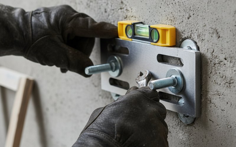
Installation is where many good CAD models die. Official drawings assume perfect hole patterns, perfectly flat walls and a patient installer with a torque wrench. Real walls are out of plane, anchors wander, and sometimes the last two holes simply do not line up.
Standard sheet metal guides tell you to respect minimum hole sizes, keep holes away from bends, and keep bend directions consistent. Those rules keep the part manufacturable. They do not make it installable.
Brackets that are easy to live with tend to share a few quiet habits. They favor elongated slots over tight holes on at least one interface. They pick slot directions that match the most common misalignment axis instead of randomly. They combine one “hard” locating hole with one or more forgiving features. They avoid stacking tolerances from multiple folded components into one overloaded bolt.
Think of a TV wall mount. Consumer guides spend time on bracket styles: fixed, tilting, full-motion; they also stress VESA pattern compatibility and wall types. Underneath that consumer advice is a simple pattern. The bracket must adapt to inconsistent stud spacing, different wall materials, and a wide range of VESA patterns. So manufacturers rely heavily on slotted patterns, multiple hole arrays and adaptor plates. That is the same thinking you want in your industrial brackets, even if the application looks unrelated.
If your design forces the installer to hit four tight holes in concrete, through a thick decorative cover, with no access for a drill template, you are not designing a bracket. You are designing rework.
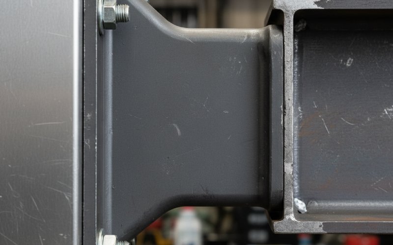
Most mounting brackets today are sheet metal. Laser cut, bent, maybe with a few PEM inserts. The design guides online are good at listing rules: minimum bend radii, distances from hole to bend, avoiding tiny features that break in forming. They protect the part from cracking during forming or from being impossible to manufacture.
Yet failures in the field often come from things those lists barely mention. Flatness. Twist. Edge bow. Secondary operations. A bracket that looks perfect in the CAD tree can arrive from the press brake with a degree or two of unintended twist. Blogs about sheet metal failures and common design errors keep returning to this point: ignoring real manufacturing tolerances and forming variability leads to cracked parts, misfitting assemblies, and surprise scrap.
When that bracket mounts onto a rigid structure, a small twist forces installers to pull it flat with fasteners, turning nominal clearance holes into stressed joints. The part “works” for a while because the screws win, until fatigue or wall damage appears.
A practical approach looks like this, although not always in this neat order. First, acknowledge that bracket flatness will never be perfect. Second, provide adjustability so the installer does not use bolt torque as a press. Third, decide where you can tolerate shims or pads and where you cannot. And last, check that your FEA includes contact and boundary conditions closer to the real clamping pattern. It does not have to be perfect. Just less imaginary.
The mounting bracket is usually the cheapest item in an assembly that sits outdoors or near vibration. It is also one of the first parts blamed when something rattles loose or corrodes.
Articles on light pole brackets and PV mounting hardware make a point that the bracket must handle not only weight but repeated dynamic forces over its service life. Similarly, automotive work on engine mounting brackets highlights how these components significantly affect noise and vibration levels in a vehicle over time. The conclusion is plain: fatigue and environmental effects are not extras; they are the main game for long-life brackets.
Corrosion is often treated as a coating selection problem. It is also geometry. Any pocket where water can sit, any tight crevice that traps salt spray, any unsealed interface between dissimilar metals becomes a slow-acting attack point. A neat flush fit in CAD can turn into a perfect crevice cell, especially where stainless fixtures meet coated carbon steel.
On vibration, small clearances mean impacts. Impacts mean fretting and loosening. A bracket that depends on nominal friction at a single joint to stay in position will, sooner or later, slide. Especially if users or maintenance staff occasionally bump it. Indexing features, keyed faces, small ribs, or even a second fastener at a shorter pitch do more for life than another millimeter of thickness.
The useful rule: when the environment is harsh, over-weight the quality of the load path and the robustness of the interfaces; treat pure static strength as the easier part of the job.
Buying brackets is boring until the first failure in the field. Then everyone cares about what went wrong in the RFQ. Sourcing-focused articles on metal brackets talk about issues like inconsistent flatness, poor surface finish, out-of-tolerance holes and weak traceability, all of which can turn a low unit price into expensive rework and quality escapes.
Things that rarely show up in simple drawings suddenly matter. Flatness spec and measurement method. Allowed twist per length. Hole positional tolerance relative to a functional datum, not just nominal edges. Coating thickness and its effect on hole clearance. Presence of sharp edges that damage cables or coatings during installation.
When you write a spec for a supplier, you are also shaping behavior. If the print is vague, the factory will optimize yield and cycle time. If the print clearly states what matters functionally and what is flexible, they can optimize without harming performance. Many bracket sourcing problems stem from leaving this unsaid. The vendor guesses. You get what they guessed.
Including a small set of functional checks in incoming inspection helps. For example, a simple go / no-go gauge for slot width at critical joints, a quick flatness check against a reference surface, or a basic fixture that reveals twist. These checks are cheap once they exist, but you have to design them and commit.
There is a huge range of standard TV mounts, shelf brackets, pipe clamps, and generic L-brackets available, reviewed endlessly by consumer sites and trade blogs. Many use similar hole patterns, steel gauges and coatings. Their strengths and limitations are quite predictable.
Using standard brackets makes sense when the host structure is predictable and the load case matches what the product was built for. A TV mount on timber studs. A light shelf on a concrete wall. A pipe clamp on a standard rail. The value is not only cost, but also that countless other installs have already tested the product.
Custom brackets start to make sense when any of these are true and persistent: the load path is unusual, the structure is non-standard, access is restricted, motion or adjustment is part of the requirement, or aesthetics impose nonnegotiable constraints on geometry.
The mistake is halfway solutions: taking a standard part and forcing it to play a different role with spacers, extra plates or odd orientations. The bracket might survive. The rest of the system might not. If you regularly find yourself stacking washers or drilling new holes onsite to “make it work”, that is a design problem dressed up as an installation trick.
The same piece of bent metal can mean different things depending on where it goes. It helps to state the trade-offs plainly.
Here is a simple way of thinking about different bracket situations and what actually deserves attention.
| Use case | Primary risk if you get it wrong | Quiet design choices that help | What usually goes wrong in practice |
|---|---|---|---|
| Consumer TV or display wall mount | Pull-out from wall, sagging, unsteady aim | Generous slots for stud spacing, clear VESA pattern, simple leveling method | Missed studs, anchors overloaded in weak plaster, bracket geometry fights cable routing |
| Industrial machine accessory mount | Fatigue at bends, misalignment into shafts | Clean load path into stiff frame, clearance around moving parts, anti-rotation features | Bracket gets used as a lever or step, holes used as alignment even when off-tolerance |
| Outdoor lighting or pole arm | Vibration-driven fatigue, corrosion attack | Drain paths, sealed interfaces, corrosion-resistant finish, no water traps | Water trapped in pockets, fasteners chosen only by thread, not environment |
| PV or rooftop mounting hardware | Progressive movement, water ingress, uplift | Verified load path into structure, known hardware capacity, compatible materials | Undersized fixings into unknown substrate, galvanic pairs ignored |
| Engine or vehicle accessory bracket | NVH issues, crack initiation at weld toes | Smooth transitions, stiffness where needed, controlled weld length and location | Stiffeners added without load thinking, welds placed at peak stress |
| Simple shelf or storage bracket | Overload, pull-out, wall damage | Honest load rating, conservative anchor assumptions, simple install sequence | Nominal rating based on perfect concrete, installed instead in brittle substrate |
None of this is complicated. The point is that the same geometry rule looks different in each row. A thin web might be acceptable on a dry indoor shelf, but a bad idea on a vibrating pole with salt spray.
Several design details keep repeating across good brackets, whether they come from sheet metal guides, mounting hardware articles or field experience. They are not exotic. The value is in applying them consistently, not occasionally.
Hole patterns want clear intent. When a hole locates the bracket, its tolerance needs to be measured from a sensible datum. When a hole is just for clamping, it can be looser, larger, possibly slotted. Mixing these roles in one feature is asking for fit-up problems.
Bend locations need context. A bend that passes close to a hole is fine in theory if you obey minimum distances, but in forming the metal flows, and the real hole center moves. The closer that feature sits to a critical interface, the more that movement matters.
Stiffness and compliance deserve balance. Many brackets become “stronger” on paper by thickening the material. Sometimes adding a small rib or changing a span is more effective. And occasionally, allowing controlled flexibility in one direction protects something more fragile downstream.
Access for tools is not an afterthought. If the installer cannot fully seat a socket or bit because of flanges, corners or nearby equipment, you get under-torqued or damaged heads. Later maintenance becomes even harder. Designing clear wrench paths and enough clearance for fingers reduces this friction more than any instruction manual.
To wrap this up, think less about adding clever geometry and more about being honest with reality. Official documents will continue to describe strength numbers, nominal loads, and neat diagrams. Real structures bring misalignment, poor access, unknown substrates, water, vibration and users who never read your torque spec.
On your next mounting bracket, you might do only a few small things differently. Draw the load path first and make the geometry follow it instead of packaging convenience alone. Add adjustability in the direction installers actually need and remove useless play elsewhere. Specify flatness, hole tolerances and coatings in a way your supplier can reasonably achieve, and then check them with simple fixtures. Treat corrosion and fatigue as default constraints, not checkboxes near the end.
None of that shows up as a glamorous feature. The bracket still looks like a piece of bent metal. But the project manager does not get a phone call about cracks, and the installer does not reach for a drill to “fix” your poor fit. In the world of mounting brackets, that quiet absence of problems is the real success metric.