Let Istar help you get started on your project with our experience and know-how!
Upload your design files and production requirements and we will get back to you within 30 minutes!

Rigid-flex PCBs are not your normal green circuit boards. They are a mix, a blend of the strong, reliable rigid PCBs we all use and the amazing, bendy flex circuits. This article is your simple guide to rigid-flex PCBs. I’ll share what I know about what they are, how they are made, and where they are used. If you want to make your electronics smaller, lighter, and more dependable, you should read this. We will look at the design and manufacture of these cool PCBs.
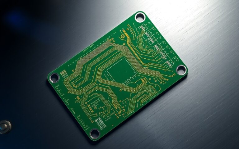
So, why is everyone talking about a rigid-flex PCB? Picture a normal printed circuit board. It’s hard and flat. You put all your electronic component parts on it. Now, picture another circuit that is as flexible as a sheet of plastic. You can bend it and fold it. A rigid-flex PCB is a special kind of board that has both. It has hard parts for holding components and flexible parts that act like built-in wires. This is a technology that combines the best of both flexible and rigid board technologies.
I remember a job where we had to fit a big electronic system into a tiny, weird-shaped box. We tried using separate rigid PCBs linked with wires and connector parts. It was messy and likely to break. Then we tried rigid-flex PCBs. The board itself could bend to fit the shape. This made putting it all together so much simpler. The final device was smaller and worked better.
These pcbs are made of layers of both hard and flexible stuff. The hard parts give the support your components need. The flex parts let the board be bent or twisted. This gives you amazing freedom in your design. You are not stuck with a flat board anymore. The flex part of the pcbs joins the hard parts, which gets rid of the need for connectors. This is a big plus for any designer. The rigid-flex pcbs offer a new kind of design freedom.
I get this question often. People ask why they should use rigid-flex PCBs when normal rigid PCBs cost less. The answer is easy: you are getting more than just a board. You are getting simplicity and a product you can count on. With normal PCBs, you often have to link many boards together. You use wires, cables, and a connector for each link. Each of those links is a spot where something can go wrong. A wire can snap, or a connector can get loose.
With rigid-flex PCBs, those links are built into the board. The flex part of the pcb is the cable. This means you have fewer components and fewer connectors. This makes your whole system more dependable. The assembly is also quicker and simpler. You don’t need to spend time wiring up different PCBs. The overall system becomes stronger because the links are printed into the flexible circuits, not wired by hand.
Think about the space you save. Wires and connectors take up room. By getting rid of them, you can make your product much smaller and lighter. This is a big advantage in today’s electronics, where everything has to be compact. So, while one rigid-flex PCB might cost more than one rigid board at first, you save money on connectors, wires, and assembly time. The long-term durability and reliability are often worth it.
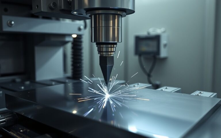
Making rigid-flex pcbs is a neat process. It is harder than making standard rigid PCBs. It starts by making the flexible circuit layers. A thin, flexible substrate material is used. The circuit design is printed on it and then put through an etch process to remove extra copper, leaving just the copper trace lines. This part of the process is like making a normal flex PCB.
Then comes the hard part. Layers of hard material, like FR-4, are made ready. These are the same materials used for plain PCBs. The amazing part is when these layers are put together. The flexible layers are carefully put between the hard layers. The whole stack is then squeezed together with heat and pressure. This sticks all the layers together into one board. This part of the fabrication needs very careful control to ensure all the layers line up just right.
After being pressed, the board is drilled. This is where holes called vias are made. These vias are coated with copper and connect the different layers of the printed circuit. This lets power flow between the hard and flex parts. Last, the board is finished. This can include adding a solder mask and printing words on the board. The manufacturing processes must be very exact to make a good final product. The fab or fabrication shop needs special equipment to work with the delicate flex materials.
I’ve talked about some of the good things, but let’s list them out. The benefits are why so many designers are using rigid-flex PCBs for their work. It’s all about making things better, smaller, and stronger.
Here are the main benefits I’ve seen in my work:
| Feature | Regular Rigid PCBs + Cables | Rigid-Flex PCBs |
|---|---|---|
| Reliability | Lower (more connection points) | Higher (fewer connection points) |
| Space Needed | High | Low |
| Weight | Heavier | Lighter |
| Assembly Time | Longer | Shorter |
| Design Shape | Stuck to flat boards | 3D shapes can be made |
As you can see, the advantage of using rigid-flex PCBs is plain, especially for tough jobs. The PCBs offer a special mix of durability and flexibility.

Designing a rigid-flex PCB is a little different from a normal PCB design. The design process needs more careful thought. As a designer, you have to think in 3D. You must plan exactly where the board will bend and how much. This is very important to do right. You have to think about the physical parts just as much as the electrical parts.
The first step in rigid-flex PCB design is to draw the shape of the board. This includes both the hard parts and the flexible “ribbons” that link them. You have to think about the “bend radius,” which is how tight the flex part can bend before it gets damaged. A good guide is to make the bend at least 10 times as wide as the flex material is thick. This helps make sure the board is reliable.
The PCB design software you use must have the capability to work with rigid-flex designs. It needs to let you mark the different areas of the board and show how it will bend. During the design stage, you also need to be careful with how you lay out your trace lines. You should not have traces that turn at a sharp corner in a bend area. It’s better to use smooth curves to lower the stress on the copper. These small design tips make a big difference. The complexity of the design means you have to pay close attention to the small things.
Yes, for sure. Component placement on rigid-flex PCBs is very important. You can only put components on the hard parts of the board. The flex parts are made to bend, and putting a component there would make it break off or hurt the flexible circuits. The hard areas give the solid base and support needed for the components and their solder connections.
When you are doing your PCB design, you must plan your component layout with care. Keep heavy parts away from the edge of the hard section where it joins the flex section. This joining area can be a point of stress. You also must make sure your placement lets the board fold the way you want without parts hitting each other. A good design will think about the final folded shape of the board assembly.
Another thing to think about is heat. Some components make a lot of heat. You need to place them so that air can move around them well, even after the board is folded into its final shape. The fabrication team will make what you design, so it’s the designer’s job to think about these physical and heat problems. The aim is to make a strong board where every component is safe.
I’ve seen rigid-flex PCBs used in so many great products. Their special capability makes them great for certain fields. Any time you need to save space, lower weight, and improve reliability, a rigid-flex PCB is a smart pick. They are very useful.
One of the biggest fields is aerospace. In planes and satellites, every bit of weight and every inch of space is important. The durability of rigid-flex PCBs is also a big plus, as they must live through strong vibration and very hot or cold temperatures. The reliability of these PCBs is key in an aerospace application where a failure is not an option. This is why aerospace engineers really like this PCB technology.
You will also see them in medical devices. Think about hearing aids, pacemakers, or portable health equipment. These devices must be small, light, and very dependable. Rigid-flex PCBs allow for the making of compact and easy-to-use medical devices. The military is another big user. They are used in radios, GPS units, and other tools that need to be tough and work in harsh environments. The automotive world also uses them in sensors and control units that are put in small spaces inside a car. Any difficult application can be helped by them.
Picking the right company to manufacture your rigid-flex PCBs is one of the biggest choices you’ll make. This is not a job for any old PCB shop. The fabrication process for these boards is very special and needs certain skills and equipment. You need a manufacturer with clear experience in flex and rigid-flex PCB technology.
When I look for a manufacturer, I always ask to see examples of their work. I want to see their capability with my own eyes. I also ask about their manufacturing processes. What kind of quality control steps do they have? How do they work with the delicate flexible circuit substrates? A good manufacturer will be glad to tell you about their process. They should be able to show you how they control things like getting the layers to line up and making the etch process the same every time.
It’s also a smart move to talk to their engineers. A good team works together. Your designer and their fabrication team should be able to talk to each other easily. This helps find possible issues early in the design process, which saves a lot of time and money. Look for a manufacturer who will work with you to make your design better for their fabrication process. Their knowledge can be a big advantage. The right manufacturer can make sure your project is a success.
In my experience, the answer is a strong yes. The better reliability comes from the main design of rigid-flex PCBs. As I said, the biggest thing is getting rid of connectors. Wires soldered by hand and physical connectors are often the weakest parts of an electronic system. They are likely to break from vibration or moving back and forth.
Rigid-flex PCBs build the connections into the board itself. The printed copper traces inside the flex ribbon are much tougher than a separate cable. This makes a much stronger and more steady electrical connection. This makes the whole device better able to withstand mechanical stress. The stability of rigid parts mixed with the bendability of the flex parts gives you a strong solution.
Think about a camera inside a moving part of a machine. A normal board with a cable would have a lot of stress on the connector. The cable might bend and break over time. A rigid-flex PCB, however, is made to bend. The flex part can handle millions of bends without failure. This built-in durability is a big reason why rigid-flex PCBs offer such a large improvement in the product’s overall reliability. The fewer parts you have, the fewer things can break.

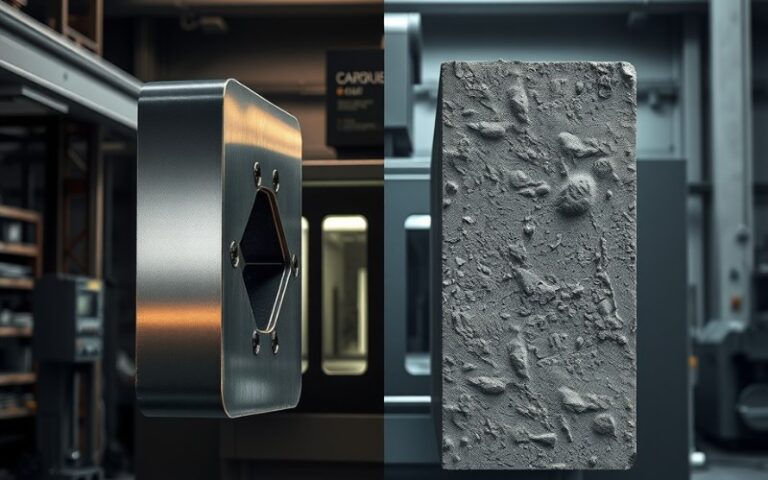
While the good parts are great, we also need to discuss the hard parts. The manufacture of rigid-flex PCBs is not simple. The complexity of the process has some difficulties. One of the biggest problems is dealing with the different materials. The hard FR-4 material and the flexible polyimide material act differently during the fabrication process. They grow and shrink at different speeds when heated. This variation can make it hard to keep all the layers lined up perfectly.
Another hard part is the pressing process. Sticking the hard and flex layers together needs very careful control of heat and pressure. If it’s not done right, the layers can come apart, which spoils the board. The delicate nature of the flex material also makes it hard to handle it during the manufacturing processes. It can be easily stretched or hurt.
Drilling the vias that link the layers is also harder. The drill must go through both hard and soft materials, which can be difficult. Lastly, the price of the materials for rigid-flex pcbs is higher than for normal PCBs. All these problems mean that the fabrication needs a high level of skill and special equipment, like advanced testing equipment. This is why picking a skilled manufacturer is so important. They will have the process controls needed to handle these problems and give you a high-quality board.